Thursday, August 16, 2012

Raspberry Pi and the WS2801


Update (October 29th):
Big update here:
http://thegreatgeekery.blogspot.ca/2012/10/pixelpi-update.html

Update (August 19th):
 - Pixel Invaders support provided in the 1.3.0-Beta4 release of pixel controller (Here: https://github.com/neophob/PixelController/downloads)
- Tested and working with the latest checked in version of PixelPi
- Run it like this: " sudo python pixelpi.py --chip WS2801 --mode all_off "
- It works by sending the pixel data to the pixelPi software using a UDP network connection.  So in pixelcontroller you must setup a UDP output device with the IP set to the IP address of your Raspberry Pi board  (Keep the port set at 6803)
- The PixelPi software receives the packet and sets the pixels accordingly.

Update (august 17th):
- Just added preliminary support for pixel invaders; Neophob (from http://www.pixelinvaders.ch) just added UDP support so the pixelcontroller software can talk to the Raspberry Pi (https://github.com/neophob/PixelController/issues/23)  Its still a work in progress but should be functional(ish)


What it does so far:
- Supports POV LED Strip (Like the original Adafruit Software)
- Now Support matrix displays (2D Panels)
- Added some test modes (fade and chase modes)
- Supports pixel remapping (by using a CSV file with the location of your pixels in the array)
- Adjustable refresh rate / chase rate
- All options selectable by command line args (no python tweaking required (hopefully))
 
What's up next.
 - panning on large images across the pixel array.  Ideally I was thinking it would be cool to pass in some images from vgamaps.com and have it pan around them.
- animation support (maybe animated GIF)
- TCP/IP support (support sending display data from another PC)


Installation:

Grab the python file:
git clone git://github.com/scottjgibson/PixelPi.git

Install Python Image library:
sudo aptitude install python-imaging-tk

UsageL
pi@raspberrypi ~/git/PixelPi $ sudo python pixelpi.py  --help
usage: pixelpi.py [-h] [-v] [--chip {WS2801,LDP8806}] --filename FILENAME
                  --mode {strip,array,fade,chase} [--verbose]
                  [--array_width ARRAY_WIDTH] [--array_height ARRAY_HEIGHT]
                  [--spi_dev SPI_DEV_NAME] [--refresh_rate REFRESH_RATE]

optional arguments:
  -h, --help            show this help message and exit
  -v, --version         show program's version number and exit
  --chip {WS2801,LDP8806}
                        Specify chip type LDP8806 or WS2801
  --filename FILENAME   Specify the image file eg: hello.png
  --mode {strip,array,fade,chase}
                        Choose the display mode, either POV strip or 2D array,
                        color, chase
  --verbose             enable verbose mode
  --array_width ARRAY_WIDTH
                        Set the X dimension of your pixel array (width)
  --array_height ARRAY_HEIGHT
                        Set the Y dimension of your pixel array (height)
  --spi_dev SPI_DEV_NAME
                        Set the SPI device descriptor
  --refresh_rate REFRESH_RATE
                        Set the refresh rate in ms (default 500ms)


Test with a fade:
sudo python pixelpi.py  --chip WS2801 --mode fade --refresh_rate 1

Test with a chase:
sudo python pixelpi.py  --chip WS2801 --mode chase--refresh_rate 1

Display an image (POV mode):
sudo python pixelpi.py  --chip WS2801 --mode strip --filename test.png --refresh_rate 1

Display an image (Array mode):
sudo python pixelpi.py  --chip WS2801 --mode array --filename test.png --refresh_rate 1


Wire up the RGB LED string:
I did something similar to this:
http://learn.adafruit.com/light-painting-with-raspberry-pi/hardware

My starting point:
http://learn.adafruit.com/light-painting-with-raspberry-pi/software

Thursday, October 27, 2011

20000 Page Views

Last week I hit 20000 page views (more than I would have expected), I'm pretty surprised especially considering the very narrow scope of my posts.

Lots of interest from Russia and Poland on many of my projects; apparently I was born on the wrong continent.

Thanks Everyone / dziękuje wszystkim / Спасибо всем

Tuesday, October 18, 2011

Powder Coating System MK-II Progress


I have had a few questions and requests for additional documentation regarding my next powder coating machine build.

I have drawn up some proper schematics of the powder coating controller including the subsections for variable HV supply.

The full controller schematic is here:


You'll notice I just specified 28VDC input; its really up to you how to obtain this; you can get cheap switching modules off ebay; laptop power supplies, or you can build your own power supply with a transformer and rectifier (My preference as its most robust option).  I didn't go into it here as its pretty standard stuff

I have also done a schematic and board for just the HV supply; again its just a simple switching power supply which drives the flyback transformer.  There are other popular flyback drivers which use the resonance of the flyback itself to set the frequency, but I have found the timer based designs easiest to build and having the easiest to obtain parts.

Here is the schematic:


And the board layout:


I'm going to have boards made for this driver; If you're interested I'll be selling them for $10 each + $2 shipping (I will just send them as "letter mail").  Let me know via e-mail or comments if you're interested as that will get me motivated to put them up on the store http://www.thegreatgeekery.com/store/


I'm also playing with the idea of moving the flyback (and a HV cascade) onto the gun,  I havn't made too much progress in this area, just a box of parts really...


Saturday, September 24, 2011

Major news in the Roomote project

Brian Pratt, the developer of the Roomote iPhone app has released the source code for the client side (iOS app) and server side Mac OS app.

I have been working on a cross platform server application but now with full access to the source code it should really speed things up.

Progress has been a little slow on my port. I have the server auto discovery working using avahi in place of bonjour, working on the command decoding from the iPhone. It looks like the Roomote iPhone app doesn't use bit packed data structures which was causing issues with my decoding.

I have finished my prototype ultra low profile Roomba Bluetooth interface, I anticipate the circuit boards arriving this week. I'll post more details on this shortly.

Many thanks to Brian for sharing his hard work and helping me with my port.

Brian's Roomote Page
http://www.brianhpratt.net/cms/index.php?page=roomote

Brians Roomote github page:
http://github.com/brianpratt/roomote

My Github page:
https://github.com/scottjgibson/roomote


Sunday, August 21, 2011

Roomba iPhone Control

Started porting the OSX interface app for the roomote iphone interface.  Essentially it allows you to use your roomba as a little remote control bot which can play music and drive around.  Also allows you to see some diagnostic stuff.

Here is my github page:
https://github.com/scottjgibson/roomote

Here is the main roomote page which has the source for the OSX app:
http://www.brianhpratt.net/cms/index.php?page=roomote

Its been slow going because I'm working on a PCB for a low profile bluetooth roomba interface.

Here is a link to the roomote iPhone App:
http://itunes.apple.com/ca/app/roomote/id335355833?mt=8

Friday, August 19, 2011

Reception of Global-TV OTA DTV in Ottawa (Kanata)

Update: Nov 27th - Finally got it; see the bottom for details


Global TV started broadcasting in Digital (HD) over the air in mid august.  Like many others I was not able to receive it.

The Problem:
Due to the DTV Transition Global-TV Ottawa (Channel-6) has changed transmitters.  Their previous transmitter was 50KW; their new transmitter is 3KW...  As you can imagine its much more difficult to tune it in now.

My original setup:
- A digiwave 4-bay UHF antenna (ANT-2048 - which I bought for $20 at Canada Computers) in an upstairs bedroom, connected to a cheap radioshack distribution amplifier I have had for years

I was able to pick up Global TV analog with this setup despite using a UHF only antenna; and Global TV being on Channel 6 (VHF-Low band).

Here is my tvfool report: http://www.tvfool.com/?option=com_wrapper&Itemid=29&q=id%3d9e748956995e10

First Attempt:
In looking for the cheapest possible solution I have decided to add a VHF-Low dipole (rabbit ears - extended horizontally) to my setup; as well as replace the distribution amplifier with a UHF/VHF combiner - amplifier

First Attempt Equipment:
- VHF Dipole (Rabbit Ears): http://www.thesource.ca/estore/product.aspx?language=en-CA&catalog=Online&category=Indoor+Antennas&product=1500235
- UHF/VHF Combiner / preamp thing:  Digiwave ANT-1028: http://canadacomputers.com/product_info.php?cPath=164_165&item_id=021144

Some thoughts on the Digiwave ANT-1028:
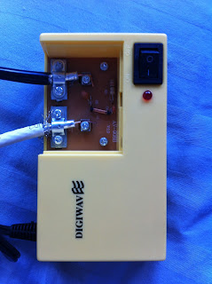
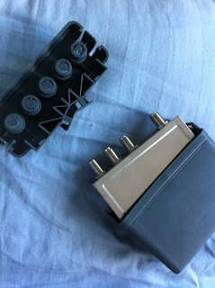
(1) Don't buy it:  its seriously made as cheaply as I can ever imagine, the F connectors were loose, its not weather shielded; the ampilfier unit doesn't have F-connectors; you have to strip your coax and clamp it on to.  The connections on the combiner / preamp are not labelled at all.  You have to take the tin box apart and read the silkscreen on the pcb (which is under the connectors) to see what they are.  No instructions.

Update:
The good part is Canada Computers is a reputable company and they allowed me to return it without issue.

Here are some pictures of the construction of the device:


Results:
Didn't give me any better performance versus just my UHF antenna :( Infact many UHF channels came in worse compared to not using the amplifier/combiner.  CJOH was slightly clearer, but not much better.

Second Attempt:
http://www.otacanada.com to the rescue.  I stumbled across this site while searching for Canadian OTA suppliers.  I was happy to discover they share a store with motofoto in the Carlingwood mall in Ottawa.  I visited one lunch hour and boy was I surprised, nice to find a small business which stocks this stuff and knows what they're talking about.  I definitely would recommend them to anyone looking for OTA stuff in Ottawa, they even have an antenna guide on their website: http://www.otacanada.com/cgi-bin/ota_recs.pl

Second Attempt Equipment:
- VHF Dipole (Rabbit Ears): http://www.thesource.ca/estore/product.aspx?language=en-CA&catalog=Online&category=Indoor+Antennas&product=1500235
- Channel Master CM-7777

CM-7777 impression:
- Huge step up from the digiwave (also more than twice the price mind you).  Build quality is excellent; its actually shielded properly, includes instructions and labelled connectors, as well as an FM trap which is good when trying to receive channel 6.


Results:
This box made a huge difference compared to not; and compared to the digiwave box.  I now receive 20 OTA channels; but unfortunately still no global...  But all other channels are clearer and have better strength.


Attempt 3: Diy Folded Dipole
I followed this guide (http://www.wfu.edu/~matthews/misc/dipole.html)  to determine the length of antenna to make.

Jeff at http://www.otacanada.com was nice enough to sell me some 300ohm wire for cheap, so for channel 6 (centered at 85MHz)
The wavelength on 300ohm twin-lead is 3.352 meters; so the antenna length is half that; at 1.676m.  I installed a 300-75ohm converter right at the antenna.

Update:
I soldered up the antenna; but no luck receiving global.  No better reception compared to rabbit ears.


Update: Moving to the antennas to the attic worked; so I gave up on this...  Attempt 4 (A)  DIY Channel 6 Tuned Yagi:
Starting to plan a build of a "Channel Cut" directional Yagi antenna tuned for channel 6.


Since it will be going in the attic; not much needed in the way of weather proofing;  So I'm going to go with a design with a wood frame and copper wire based directors / reflector.


Planning a design similar to this:
http://members.ziggo.nl/astrid.vanunnik/446/446pmrantyagi.htm


I have decided that before I attempt taking on a new antenna; I'll move my setup to the attic

Attempt 4 (B)  Antennas to the attic:
I'm in progress of moving my antennas to the attic of my home; I don't want to put them outside for cosmetic reasons, so I thought I would try the attic before building a new antenna (which would need to go in the attic anyways).


having a house built in the 80's there is no convenient way to get the wire into the attic.  I have resorted to running the coax to the second floor via a cold air return; then going to the attic in the corner of the closet (which backs on to the same cold air return).  Not an easy task as the cold air return has some corners in it.  I have had success using a wire pulling fish.  I am using this one: http://www.princessauto.com/workshop/hand-tools/measuring-tools/distance-measuring/8067944-50-ft-fish-tape-with-lighted-end it works quite well (though I have never bothered with the illuminated end) and its cheap and available locally.

Update - Nov 27th 2011


Finally got some coax to the attic.  No luck getting global with rabbit ears; but I finally had success with my home made folded dipole.  With everything pointed properly I know get all of the local stations!  So I'm using my home made channel folded dipole pointed at camp fortune; and my 4 bay UHF pointed at HC.  These antennas are combined with a CM-7777.


Resources;
Global-TV Ottawa Reception Thread:http://www.digitalhome.ca/forum/showthread.php?t=143890
Current Digital TV Broadasting Status: http://www.user.dccnet.com/jonleblanc/Canada_TV_Stations/DT.html


Tuesday, August 9, 2011

Roomba router fail...

So I got my little linux router all fixed up and connected to the roomba.  I compiled a little test program to send some commands to the roomba to make it move, it worked!

Now I went on to power the router via the SCI port on the roomba.  From what I have read the power is essentially a tap directly off the battery.  So I connected it up and it worked, at first...

Shortly after connecting it the roomba started making the uh-oh sound, over and over again; :(  So I powered it off and back on with everything disconnected and it kept making the same sound; plugged it in to charge; same sound.

The only way that I could get it to stop making sad noised was to do the battery reset procedure.

Starting to work on a plan-B for networking the roomba; going with a simple bluetooth serial bridge.